
Information Note 97/05
Demonstration of COFDM Digital Television to the Prime Minister's Science & Engineering Council.
By Neil Pickford

Executive Summary
The Prime Ministerís Science and Engineering Council met on the 30th of May 1997 for an event called Innovations. As part of the presentations a demonstration of Digital Television was given to the Council including the Minister. This Information Note details the Digital Television demonstration which consisted of both transmission and reception equipment operating within the confines of the main committee room at parliament house.
The demonstration showed that digital television is now a reality and that real hardware is available. Viewers who are currently receiving degraded PAL signals can expect significantly better pictures through digital television.
The flexibility exists within the digital television systems to provide multiple conventional definition, or high definition television services and scope for other new data services.
Digital television can provide these services while utilising the same spectrum requirements as the existing television system with potential in the future to use it more efficiently.
During the course of the set-up and conduct of the demonstration some practical information about digital television technology was highlighted.
Introduction
The Prime Ministerís Science and Engineering Council met on Friday the 30th of May in the Main Committee room at New Parliament House. During the morning a series of presentations were given highlighting aspects of a report from the Radio and Telecommunications Working group. The event was called Innovations. Three demonstrations concentrating on new and innovative wireless technology were part of the presentations.
This Information Note details the Digital Television demonstration for which the Communications Laboratory provided technical and equipment support.
Digital Terrestrial Television
Since the 1950s we have possessed the technology to broadcast television using analog picture transmission and storage techniques. However, although it has been possible to digitise these pictures, the large amount of information produced, in doing so, has made it difficult to broadcast this digital information to the general population. Digital images have the advantage that they convey near perfect copies of the original images unlike analog systems which always degrade the original image each time the image is passed from device to device.
Over the last few years huge advances in the compression and coding of moving images have resulted in the development of Internationally agreed standards such as JPEG and MPEG-2. With these standards it has now become possible to reduce the amount of information in a digitised visual image so that it is now possible to convey those images using the same size slots of broadcasting spectrum which are currently used for analog television.
Currently there are a number of systems being developed around the world to convey this digital information to the home using new and innovative modulation techniques. The modulation system used in this demonstration is Coded Orthogonal Frequency Division Multiplex (COFDM). This system uses thousands of very closely spaced radio carrier waves as a group to convey the digital image information. The system being demonstrated was developed in Europe by a company called Digital Media Vision (DMV) and complies with the European DVB specification.
The Demonstration
The Demonstration consisted of both transmission and reception equipment operating within the confines of the main committee room at parliament house.
The transmission equipment radiated both a normal PAL television signal and a Digital COFDM signal into the main committee room at a power level of 10 mW. The COFDM signal occupied UHF channel 44 and the PAL signal occupied UHF channel 45, in a similar manner to that proposed for introductory phase of Digital TV in Australia. Both the PAL and Digital signals were adjusted to equal power levels for the demonstration.
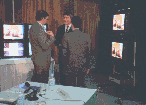
The Receiving equipment was placed on a mobile trolley (RHS Picture 1) to allow demonstration in front of the committee. A Tandy indoor UHF TV antenna was used to receive the signal which was split equally and fed to two identical television receivers. The bottom receiver was tuned to the PAL signal while the top receiver was fed with video from the Digital COFDM receiver. In this way a simultaneous demonstration of the quality of the received pictures was available to the committee.

Picture 1 - The Demonstration Equipment. Gordon Drury (Left) talks to a participant assisted by Jeff Gledhill (Right)
The Digital COFDM receiver provided an output of the digital image data which was fed by cable to a bank of three MPEG-2 decoders and four picture monitors to the side of the room (LHS Picture 1). These were used to show that the digital television signal being transmitted across the room contained a total of 4 television pictures while the existing PAL system can only accommodate one picture.
Equipment Layout
Transmission Equipment
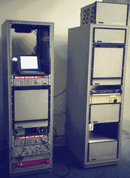
The equipment shown in Figure 1 was used to produce the signals for the demonstration. The majority of this equipment was housed in two 19 inch equipment racks located in the committee room foyer area. See Picture 2.

Two off air video sources were provided by the sound and vision unit at parliament house and these augmented two Betacam video tape sources. The four video channels were fed to DMV MPEG-2 encoders which coded the first digital channel at 8 Mb/s and the remaining channels at 3 Mb/s. The total video channel loading was 17 Mb/s. The Digital Betacam supplied the video for this first digital channel via itís Serial Digital Interface (SDI).
The coded digital video streams were multiplexed and fed to the COFDM coder producing a 7 MHz channel at an IF of 35.3 MHz. This IF was then upconverted to channel 44 UHF. A Telonic bandpass filter was used to remove unwanted mixing components before the signal was combined in a 3 dB hybrid combiner with the PAL Signal.
The Digital Betacam source was used to feed the PAL IF modulator via a Audio/Video delay unit which delayed the PAL signal to compensate for the digital stream processing delays. The PAL signal was then upconverted to channel 45 and filtered with a Telonic bandpass filter.
The combined PAL and COFDM channels were amplified by a 38 dB linear amplifier producing around 10 mW of signal which was transmitted into the room using a horizontally polarised UHF log periodic antenna. The antenna was mounted in a spare camera booth at the back of the room. The distance to the receive antenna was approximately 20 metres and the COFDM and PAL power levels were adjusted to be within 1 dB of each other.
Figure 1 - Digital TV Coding & Transmission Equipment Layout

Receiving Equipment
The receiving equipment is shown in Figure 2 above. A Tandy UHF indoor TV antenna was used to feed both the COFDM digital receiver and a normal domestic television with equal signal levels via a 3 dB splitter. A 6 dB pad before the splitter was used to adjust the signal level so that the systems were close to their threshold of failure.
Originally it had been planned to use the video direct from the Pace MPEG-2 decoder which is part of the DMV COFDM receiver however as some software lockup/recovery problems were evident when the transmission channel failed it was decided to use video from one of the separate video decoders.
The complete digital data stream was transported from the COFDM receiver, on the mobile trolley, to a table at the left front of the room using a Low Voltage Differential Signal (LVDS) which utilises a DB25 type cable. This signal was split three ways to feed three MPEG-2 decoders allowing access to each of the four video data streams contained within the digital multiplex. As shown in the diagram each of the decoders, including the COFDM receiver on the mobile trolley, fed one of the 4 monitors allowing all the video streams to be observed during the demonstration.
On return of the equipment to the Laboratory the C/N threshold of the UHF COFDM receiver was measured as 20 dB and the minimum signal level found to be 30 dBuV. These figures indicate that the UHF COFDM receiver has a noise figure of around 7 dB.
The Presentation.
Mr Gordon Drury of DMV (UK) gave the demonstration of the system to the council members. Gordon made the following points in his presentation:
Observations
During the setup of this low power simultaneous demonstration of Digital and Analog television the following points of interest were observed.
Latency
The television channel which was being coded at 8 Mb/s had a delay of 1.44 seconds (36 frames). This was the delay that was required to be inserted in the Analog television path to compensate for the overall digital system processing delay. It can be expected that if a channel is being coded at a lower bit rate more processing time will be required and even greater latency could be experienced. This means that up to 1.5 seconds latency can be expected in digitally transmitted signals. When the LVDS digital decoder was substituted for the internal Pace decoder an additional frame delay was added to the digital systems latency.
MPEG Decoders
The Pace MPEG-2 decoder installed inside the COFDM receiver showed intermittent lock-up brought on by received noise and is due to software problems. The Pace decoder is a commercial unit, similar to that in use by Galaxy in Australia, which has been interfaced to the COFDM receiver data. Unfortunately the software in the two individual systems do not work together. The demonstration was rewired to use one of the separate decoders for the digital picture on the trolley to work around this problem. The signal from the Pace decoder was fed across to the 4 monitors to show the additional channels. During the actual demonstration no real problem occurred however the DMV engineers felt more at ease with the separately decoded signal.
Interoperability
The software/interface problem with the Pace MPEG decoder highlights the larger issue of interoperability. Even though we have a world standard for the compression and coding of conventional and high definition television data there does not appear to be a standard interface for these signals. This emphasises the simmering interoperability and interfacing problems which exist between equipment from differing manufacturers. At present no manufacturer will guarantee that their equipment will work with that from another source. Each seem to be implementing different interfaces and control software. Unless these personality and interfacing problems are solved the consumer will be faced with digital equipment which can only be interfaced to other equipment from the same manufacturer.
Ghosts
The Digital system performed well on the short ghosts experienced within the room compared with PAL however both systems failed when the antenna was oriented to produce a relatively flat signal fade. These flat fades are caused by very short & strong echoes.
Power Level
When operating the Digital signal either 12 or 17 dB below the PAL signal power the Digital signal dropped out or froze regularly while acceptable Grade 4 PAL pictures were being displayed. When the two systems were operated at the same power level the PAL signal had a picture rating of less than 3 when the digital system failed. This phenomenon is thought to be due to environmental noise levels being of similar level to the transmitted signal. During the setup of the demonstration it was noted that when overhead lighting was turned on, hum/interference bars were easily visible in the PAL signal and the Digital TV equipment experienced greater difficulty decoding the signal. For this reason these lights were requested to be off during the demonstration.
Cooling
The racks that the MPEG encoders were mounted in had solid sides which could not be removed. After around 15 minutes operation the MPEG Coders started signalling system alarms due to the internal temperature exceeding 55 degrees Celsius. The MPEG coders take fresh air for cooling from their right side and expel it on the left side. With four encoders and a multiplexer in the same rack there proved to be insufficient ventilation. To solve this problem the second encoder was removed and placed on top of the rack for the duration of the demonstration as can be seen in Picture 2. This allowed more cool air to circulate around the remaining equipment in the rack.
Shielding
After the Demonstration when the equipment returned to the Laboratory and was setup in the test rig as before, it was found that the VHF receivers minimum signal level performance had degraded by around 7 dB. During the demonstration set-up, a new version of the equaliser software had been fitted to this receiver. It was found that the earthing of the tuner to the receiver case as well as good connection of the smc RF input connector was required before the originally measured minimum signal level could be repeated. It seems that the earthing of the shield around the tuner inside the receiver has a significant effect on the receivers minimum signal level performance. The tuner was later earthed with a wide copper braid to two places on the case. This has stabilised this problem.
Conclusion
The demonstration showed visibly that digital television is now a reality and that real hardware is available. Viewers who are currently receiving degraded PAL signals can expect significantly better pictures through digital television.
The flexibility exists within the digital television systems to provide more conventional definition, or higher definition television service(s) with scope for other new data services.
Digital television can provide these services while utilising the same spectrum requirements as the existing television system with potential in the future to use it more efficiently.
At the very low power levels being used during this demonstration both systems required similar power levels to operate correctly. It is thought this is mainly due to the transmission levels being close to the noise level present in the demonstration environment. When more normal power levels are in use it is expected that the digital system will operate with approximately 13 dB (20 times) less power than the current PAL systems.
The digital system introduces a different failure mode to that experienced by television viewers in the past. The system either works, perfectly, or freezes and does not work at all. Due to the processing involved in digital systems a transmission latency of in excess of one second will be experienced.
Further international standardisation of interfacing and operation of functionally equivalent equipment needs to be addressed so that equipment from differing manufacturers will operate together.
Acknowledgments
I would like to thank the following persons and organisations who contributed to the successful staging of this demonstration.
Staff of the Communications Laboratory
Mr Jeff Gledhill - DMV - UK
Mr Gordon Drury - DMV - UK
Mr David Johnson - News Data Systems
Mr John OíSullivan - News Data Systems
Mrs Helen Wilson - DIST
Mr Peter Jauncy - Sound and Vision
News Data Systems - Broadcasting Division
for making the COFDM Digital TV equipment available.
Return to 1997 Reports
Return to Lab Home