Figure 45
Guard Interval Utilisation

5.3.3 Multi-Carrier Modulation (MCM)
Orthogonal Frequency Division Multiplexing is the most commonly proposed MCM system.
5.3.3.1 Orthogonal Frequency Division Multiplexing (OFDM)
The OFDM concept is based on spreading the data to be transmitted over a large number of carriers, each being modulated at a low bit rate. In a conventional frequency division multiplex the carriers are individually filtered to ensure there is no spectral overlap. There is therefore no inter-symbol interference between carriers but the available spectrum is not used with maximum efficiency. If however, the carrier spacing is chosen so the carriers are orthogonal over the symbol period, then symbols can be recovered without interference even with a degree of spectral overlap. For maximum spectral efficiency, the carrier spacing equals the reciprocal of the symbol period. The multiplex of carriers may be conveniently generated digitally using the inverse Fast Fourier Transform (FFT) process.
Preferred implementations of the FFT tend to be based on radix 2 or radix 4 algorithms, or some combination of radix 2 and 4. This preference leads to the number of carriers generated in practical OFDM systems being some power of 2. Example systems are based on 2048 (2k) carriers and 8192 (8k) carriers. However, the number of actual carriers transmitted is always smaller than the maximum number possible, as some carriers at either edge of the channel are not used. These unused carriers make a frequency guard band which allows practical IF filtering. The active carriers carry either data or synchronisation information. Any digital modulation scheme may be used to modulate the active carriers, e.g. QPSK, n-QAM or n-DAPSK where n is commonly 16 or 64.
OFDM, due to its multicarrier nature, exhibits relatively long symbol periods, around 224m s in a 2k system. This long symbol period provides a degree of protection against inter-symbol interference caused by multipath propagation. This protection can, however, be greatly enhanced by use of the guard interval. The guard interval is a cyclic extension of the symbol, in simplistic terms a section of the start of the symbol is simply added to the end of the symbol. The guard intervals for the 2k and 8k systems are 1/32 of the symbol period (7/28m s) 1/8 of the symbol period (28/112m s) and 1/4 of the symbol period (56/224m s) and 1/2 of the symbol period (112/448m s). As the proportion of the symbol used to make the guard interval is increased the transmission capacity decreases. However, if a system with a greater number of carriers was used the symbol period would increase and therefore the same proportion of guard interval would give a greater protection in terms of absolute time. For example an 8k system with a symbol period of 896m s and a 1/4 of symbol period guard interval results in a 224m s guard interval. However increasing the number of carriers impacts the receiver complexity and the ability to track time-varying channels, so a trade-off is necessary. Figure 45 shows how the FFT sampling window, which is equivalent to the symbol period can be positioned within the symbol and guard interval to minimise Inter Symbol Interference (ISI).
Figure 45
Guard Interval Utilisation

OFDM when coupled with appropriate channel coding (error correction coding) can achieve a high level of immunity against multipath propagation and against co-channel interference e.g. NTSC, PAL, SECAM. OFDM systems also offer the broadcaster great flexibility as bit rate can be traded against level of protection depending on the nature of the service. For example, mobile reception of the OFDM signal may be possible given due consideration to factors including vehicle speed, carrier spacing, data rate and modulation scheme, whereas, for a service with fixed reception, high order modulation schemes and consequently high data rates could be used.
OFDM signals also allow the possibility of single-frequency network (SFN) operation. This is due to OFDM’s multi-path immunity. SFN operation is possible when exactly the same signal, in time and frequency, is radiated from multiple transmitters. In this case at any reception point in the coverage overlap between transmitters, the weakest received signals will act as post or pre-echoes to the strongest signal. However, if the transmitters are far apart the time delay between the received signals will be large and the system will need a large guard interval.
The choice of main parameters for the OFDM system is determined from the requirement for SFN operation.
The carrier spacing in an OFDM system is inversely proportional to the symbol length to achieve orthogonality, for which reason the number of carriers in a channel is determined from the symbol length. In order to obtain a reasonable useful bit rate the maximum guard interval which can be used is approximately 1/4 of the active symbol length. In an SFN, signals from different transmitters arriving outside the guard interval will result in interference.
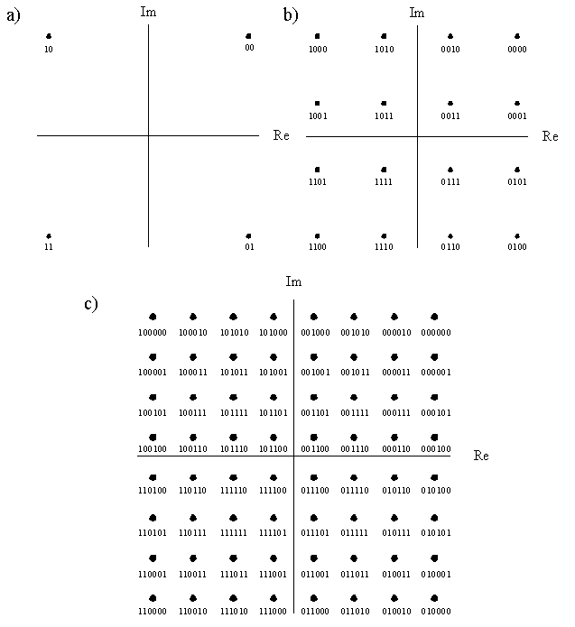
There are two main possible digital modulation techniques for OFDM systems. The first technique uses n-QAM modulation, synchronisation signals and ‘scattered pilots’. The second technique uses n-DAPSK modulation and some continual pilot carriers. Both systems also carry transmission parameter signalling (TPS) information. The TPS carries information about the transmitted signal e.g. code rate and type of modulation. Figure 46 provides a diagrammatic comparison of various modulation system constellations.
Figure 46
Comparison of modulation state Constellations

Figure 47
Constellation diagrams of a) DQPSK, b) 16-DAPSK and c) 64-DAPSK
|
a) |
b) |
c) |
|
|
|
|
Although the use of the guard interval removes the effect of inter-symbol interference under multipath conditions, it can not remove the effect of frequency selective fading. Under these conditions the amplitude and phase of each subcarrier is distorted. If the OFDM receiver is to coherently demodulate the signal it needs to equalise the phase and amplitude of each carrier. This can be done after the FFT using a simple equaliser. This process is known as Channel Estimation and Equalisation. Different techniques are proposed to estimate the channel and therefore equalise the signal for QAM and DAPSK. The n-QAM system uses a set of scattered pilots in the frequency and time domains with interpolation filtering to estimate the channel response. The n-DAPSK system derives the channel response for each carrier from the data using simple recursive filter techniques to estimate and correct phase and amplitude errors. Another technique that does not require the use of pilot carriers is that of filtered decision feedback channel estimation and demodulation. It is an OFDM symbol based fast channel estimation scheme that can quickly adapt to channel variations. Since pilots are not used, higher spectrum efficiency can be achieved.
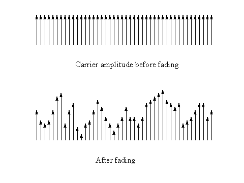
In the case of frequency selective fading, or when an OFDM signal is subject to analogue co-channel interference some carriers will be affected to a greater extent than others. Figure 48 shows that in the case of frequency selective fading, the S/N ratio will be lower on some carriers than on others. In the case of co-channel interference the carriers near the analogue sound and vision carriers will suffer a much greater interfering signal than those elsewhere in the OFDM signal. Channel state estimation is the process of estimating how much each carrier is affected by the combination of frequency selective fading and interference. This channel state estimation information can be passed to the error correction subsystem which can use the information to modify the soft decision information for each recovered bit of data. The Viterbi decoding algorithm as specified in the inner decoder of the error correction subsystem is perfectly suited to making use of the soft decision information generated by the channel state estimation subsystem.
Figure 48
Effective of frequency selective fading on carrier amplitude

The Table below provides a typical selection of the characteristics of OFDM systems in an 8MHz channel with appropriate guard intervals. All figures are in Mbit/s.
TABLE 13
System Comparison for Soft Decision Decoding (Required C/N for BER= 2x10⁻⁴
after Viterbi Decoder)
|
4-QAM 1 |
4-DPSK |
||||||||
|
Code rate |
Data rate2 |
AWGN channel |
Rice channel |
Rayleigh channel |
Data rate |
AWGN channel |
Rice channel |
Rayleigh channel |
|
|
1/2 |
4.7 |
2.7 |
3.2 |
4.6 |
5.4 |
5.4 |
6.0 |
7.4 |
|
|
2/3 |
6.3 |
4.3 |
4.8 |
7.0 |
7.1 |
7.1 |
7.9 |
10.8 |
|
|
3/4 |
7.1 |
5.3 |
5.9 |
9.7 |
8.1 |
8.1 |
9.1 |
13.3 |
|
|
16-QAM 1 |
16-DAPSK |
||||||||
|
1/2 |
9.4 |
8.2 |
8.8 |
10.8 |
10.8 |
13.5 |
14.0 |
16.2 |
|
|
2/3 |
12.5 |
10.5 |
11.0 |
14.3 |
14.3 |
16.0 |
16.5 |
19.2 |
|
|
3/4 |
14.1 |
11.5 |
12.3 |
16.5 |
16.1 |
17.3 |
17.7 |
21.0 |
|
|
64-QAM 1 |
64-DAPSK |
||||||||
|
1/2 |
14.1 |
13.5 |
14.1 |
16.0 |
16.1 |
18.4 |
19.2 |
21.2 |
|
|
2/3 |
18.8 |
15.7 |
16.4 |
19.6 |
21.5 |
21.5 |
21.8 |
24.3 |
|
|
3/4 |
21.2 |
17.3 |
17.9 |
22.2 |
24.2 |
22.8 |
23.5 |
26.8 |
|
1
Note - For the QAM perfect channel estimation had been used.2
Note - The data rate for the M-QAM is calculated under condition a real channel estimation is used. An overhead of about 12.4 % for pilot cells and synchronisation symbols has been taken [1].By inserting pilot carriers spread in time and frequency, the receiver can use time and frequency interpolation to follow changing channel conditions. Pilot carriers can also be used in the receiver for phase error correction.
5.3.3.2 Band Segmented Transmission Orthogonal Frequency Division Multiplexing (BST-OFDM)
It is not necessary that the carriers in an OFDM ensemble be continuous. It is possible to omit some carriers in an otherwise continuous array so as to minimise interference to or from a distant co-channel analogue signal. An OFDM signal can be segmented and combined in a frequency band while retaining orthogonality. The proposed "band-segmented transmission" (BST) is an example of how the technology can be applied to provide flexibility in frequency usage (and thereby make use of vacant channel slots in an otherwise congested band) and provide extendibility for future systems.
Return to DTTB Tutorial Table Of Contents