3.1 Definitions
3.1.1 Source and channel coding
Classical communications theory (i.e. based on the work of Shannon) shows that, under certain assumptions, it is possible to separate operations involving data compression and generation of signals for transmission so that they can be dealt with and optimized independently. This is where the concepts of separate source coding and channel coding arise.
3.1.2 Source coding
Source coding involves only characteristics of the source. That is, the communications channel characteristics have no influence on the source coding. Source coding exploits the inherent redundancy in the source signal to reduce the amount of data to be transmitted. This data compression stage may be loss-less or, in the case of video and audio signals, it could introduce some signal degradation. Any operation that looks at the characteristics of the source signal and takes advantage of them for the purposes of data reduction is source coding.
3.1.3 Progressive scanning
Progressive scanning in a raster-based sequence of images simplifies, to some extent, the filtering and interpolation used to convert among formats with different numbers of scan lines, different numbers of samples per line, and different temporal sampling (i.e., picture rate), Since the MPEG-2 algorithm can process complete pictures, progressively-scanned sources can be accommodated and a 24 frame/second film mode can be provided.
3.1.4 Square pixels
For computer graphics, equal geometric spacing among horizontal samples on a line and among samples displaced vertically is desirable for simple rendering of objects that may be transformed after creation. Picture elements (pixels) that exhibit equal horizontal and vertical geometric spacing are termed square pixels.
3.2 Benefits
Digital Television gives many benefits in terms of quality and flexibility, but in its raw form occupies a much greater bandwidth than today's analogue signals. A DTTB service must be able to offer 4:3 and 16:9 aspect ratio component pictures and at a minimum be capable of handling a source resolution of 720(h) x 480(v) samples per frame (ITU-R BT.601 luminance) as provided for in Recommendation ITU-R BT.1208.
In the absence of transmission errors, the picture quality would be that offered by the low bit rate redundant data reduction coding. Such quality is not constant, but is highly dependent on the particular content of the picture material being coded. At the end of 1995, work, therefore, continued on methods of assessing picture sequence criticality in order to develop techniques for determining the service quality of low bit rate coded pictures.
3.3 Low bit rate video coding and service quality
A conventional and HDTV studio signal is compressed with image coding for a lower data transmission rate and transmitted with digital modulation over a conventional VHF/UHF channel, with a bandwidth of 6, 7, or 8 MHz.
Apart from image information, capacity is also required for audio, data services like teletext and forward error correction coding (FEC). An example of bit rates for various services is as follows:
|
Video |
24 Mbit/s |
(motion-compensated hybrid DCT coding) |
|
Audio |
approx. 400 kbit/s |
(5 mono audio channels) |
|
Data |
64 kbit/s |
(undefined content) |
|
FEC |
2 Mbit/s |
(Reed-Solomon, such as RS (224, 208) or RS (227, 207)). |
3.4 Examples of video scanning standards
(a) Spatial formats
1920 x 1152, 1920 x 1080, 1920 x 1035, 1440 x 1152, 1280 x 720, 960 x 576, 720 x 576, 720 x 480, 704 x 480, 640 x 480, 352 x 240
(b) Temporal formats
23.98, 24, 25, 29.97, 30, 50, 59.94, 60
Interlaced or progressive
3.5 Video compression and coding[1,2]
3.5.1 Introduction
The digital terrestrial television broadcasting (DTTB) system is designed to transmit high quality video and audio over a single 6, 7, or 8 MHz terrestrial channel. Modern digital transmission technologies can deliver a maximum of between 17 Mbit/s and 20 Mbit/s to encode video data within a single 6, 7, or 8 MHz terrestrial channel. This means that encoding a HDTV video source whose resolution is typically five times that of the conventional television (NTSC, PAL or SECAM) resolution requires a bit-rate reduction by a factor of 50 or higher. To achieve this bit-rate reduction, there is world-wide agreement on the use of MPEG-2 video coding. In order to meet the requirements of the many applications and services envisioned, the DTTB system must accommodate both progressive and interlaced scanned pictures across a broad range of spatial and temporal resolutions. Video compression may represent the severest challenge to the DTTB system.
3.5.2 Introduction to MPEG
The Moving Picture Experts Group (MPEG) is an international group formed under the auspices of the ISO and IEC. It is formally known as ISO/IEC JTC 1/SC 29/WG 11.
MPEG's original terms of reference were to provide a "generic coding method of moving picture images and of associated sound for digital storage media having a throughput of up to about 10 Mbit/s. The coding method to be defined is expected to have applications in many other areas as distribution and communication".
The development of standards was split into two phases - MPEG-1 and MPEG-2.14
MPEG-2 was later extended to encompass HDTV (also loosely referred to as MPEG-3). MPEG-1 commenced in 1988 and was concerned with compressed video at bit-rates around 1.5 Mbit/s. This was appropriate for mass storage devices such as CD-ROMs and transmission on 1.554 and 2.048 Mbit/s PDH digital channels. MPEG has registered the committee document of this standard as ISO/IEC 11172.
Development of the MPEG-2 standard commenced in July 1990. The aim was to define a standard for the coded representation of audio-visual information providing broadcast quality at data rates up to 15 Mbit/s, based on the Recommendation ITU-R BT 601 digital television standard. In November 1991 MPEG carried out a program of formal subjective tests on a total of 32 video coding algorithms from Europe, North America and the Far East. Following this evaluation a Test Model algorithm was defined. It uses a hybrid-DCT approach (refer to Section on Digital Compression Techniques) and provides flexibility for further improvements.
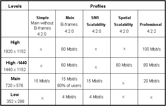
At the March 1993 MPEG meeting in Sydney and the July meeting in New York the MPEG "Profiles" and "Levels" specifications were essentially finalized. Table 1 provides a brief definition of the five Profiles and lists the pixel resolutions that characterize the four Levels. It also indicates the maximum bit rates applicable to the valid Profile/Level combinations. From a broadcaster's perspective the standard will accommodate:
It is expected that most of video requirements will be met by the Main Profile/Main Level specification. Note this does not provide for 4:2:2 sampling.
TABLE 1
MPEG-2 profiles and levels

x = invalid combination
At the New York meeting it was decided to initiate the development of a MPEG-4 standard for very low bit rate coding of video and audio with the objective of producing a draft specification by 1997.
MPEG works in close liaison with other standardization bodies, particularly ITU-T, ITU-R and SMPTE. ITU-R Task Group 11/3 on Digital Terrestrial Television Broadcasting is taking an active interest in MPEG standards.
The most significant point to note is that MPEG standards are not precise hardware implementation standards but rather generic descriptions of how the compressed set of video, audio and data signals will be multiplexed into a stream of digital packets for transmission. This standardization of the coding will in turn allow the decoder function to be standardized. In this sense the standard "presumes" the use of certain encoder hardware functions. It is therefore quite possible for different manufacturer's implementations of MPEG encoders to display differing picture quality.
3.5.3 Digital compression techniques
All current television systems contain redundant information, that is information which is not required to faithfully convey the picture between two points in a network. A modest degree of compression can be effected by simply removing this information before transmission. As this does not affect the picture quality it is referred to as a "lossless" compression technique. For example most of the sync information can be removed from a PAL/NTSC video signal.
However to obtain higher compression ratios, techniques have to be employed which do affect picture quality, albeit it by a very small degree. These are characterized as "lossy" methods. The particular lossy methods which are utilized in the MPEG and similar types of compression systems are described in this section. The descriptions relate to progressively scanned pictures, however it should be noted that MPEG-2 allows for the coding of both progressive and interlaced pictures.
3.5.4 Inter-frame prediction coding and motion compensation
A powerful method of reducing the information bit rate is to derive a prediction of the picture element (pixel) in question from the previous picture frame. The difference between the actual picture pixel value and its predicted value is then transmitted.
In most pictures the difference (error) value will be small as there is a significant degree of commonality (temporal redundancy) between successive frames. As will be explained later, transmission of a small range of values for most of the time allows the bit rate to be markedly reduced. In the decoder the same prediction process or algorithm recreates the prediction value and the transmitted difference value is added to this to derive the original pixel amplitude.
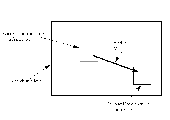
To improve the prediction process, a macroblock of 16 x 16 pixels in the current field is compared with all the 16 x 16 blocks over a defined search area in the previous field. The block which provides the best match is selected and is subtracted from the current block.
This matching process minimises the difference values transmitted and, in particular, compensates for movement of objects within the picture. It is referred to as motion compensation. The vector value which defines the relative spatial relationship of the "best fit" block to the current block - refer Fig. 2 - is coded and transmitted to the decoder.
Figure 2
Motion compensation

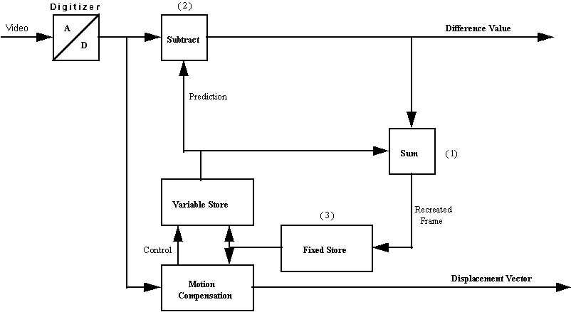
The block diagram shown in Fig. 3 provides the essential functional elements necessary for predictive coding.
Figure 3
Inter-frame predictive coding

The fixed store holds the previous frame; the variable store is used for block matching. The summing unit (1) replicates the inverse action of the decoder i.e. inverse action of the differencing unit (2). By including it in the encoder's feedback loop the encoder is able to track and correct for picture discrepancies between the encoding and decoding functions.
Although this description assumes the prediction is formed from the immediate past frame, both MPEG-1 and MPEG-2 allow the prediction to be based on a frame occurring several frames before the current one (refer to § 3.5.11).
3.5.5 Intra-frame coding
To start off the encoding process the fixed store (3) is initially filled with "null" values. The current frame is then directly coded without reference to a predicted frame. This establishes a reference for the decoder. It is normal practice to transmit such an intra-coded reference frame to the decoder from time to time to prevent the possible accumulation of any prediction or transmission errors.
3.5.6 Discrete Cosine Transform (DCT) Coding
The method used in the MPEG coder for transform coding of video is the Discrete Cosine Transform (DCT) method. DCT converts a block of typically 8 x 8 pixels from the two-dimensional spatial domain to the frequency domain - hence the term transform coding.
In Fig. 4 a grey scale (a) is represented by its amplitude values (b) and then transformed to frequency coefficients (c). Horizontal frequency terms increase from left to right, vertical frequency terms from top to bottom. Hence the upper left-hand corner represents the zero-frequency or DC (average) term, the lower right-hand the highest frequency term.
Note that the transform process in itself does not result in any bit reduction as the same number of bits per coefficient is required for the transformed block as the original block. The key to the process is that the transformed frequency coefficients are more suitable for subsequent bit-rate reduction techniques. In particular the trend for the transformed picture blocks to contain zero or near zero coefficient values - there are 60 "0's" in the grey scale example - can be used to advantage.
In practice in the MPEG video encoder the DCT is applied to the picture frame after it has been subjected to Inter-Frame Prediction coding. Hence the amplitude values before transforming are generally small and this further enhances the trend for the transformed block to contain small coefficients. As a further generalization the block matching (motion compensation) process is closer for low frequency picture content than high frequency detail. Hence the high frequency DCT coefficients can be expected to be larger in amplitude as they represent the difference due to the inexact matching. The same comment does not apply when the input to the DCT is an intra-frame coded picture as no motion compensation is employed. Coding is effected in 8 x 8 pixel blocks.
Figure 4 - DCT Coding

|
(a) |
(b) |
(c) |
3.5.7 Coefficient quantisation
In any pulse-code-modulation (PCM) process the input signal is sampled on a repetitive basis and the sampled values are assigned code values corresponding to their amplitudes. To minimise any distortion, the quantisation step, i.e. the change in input signal amplitude to move from one code value to the next, must be small. For example in high quality audio, 16-bit coding (65 536 steps) is commonly used. If higher distortion can be tolerated then the number of steps can be reduced.
In video it is well known that the eye is less sensitive to high frequency detail and hence the high frequency DCT coefficients can be more coarsely coded, i.e. fewer quantising steps, than low frequency coefficients without any perceptible loss of picture quality. This is carried out by dividing the coefficients by a value, "n", greater than one and rounding the result to nearest integer (in a digital sense). The weighting factor, n, varies according to the position of the coefficient in the block with higher frequency coefficients attracting larger values of n.
The computing of the "quantising matrix" which contains the values of n for a given picture block also takes into account:
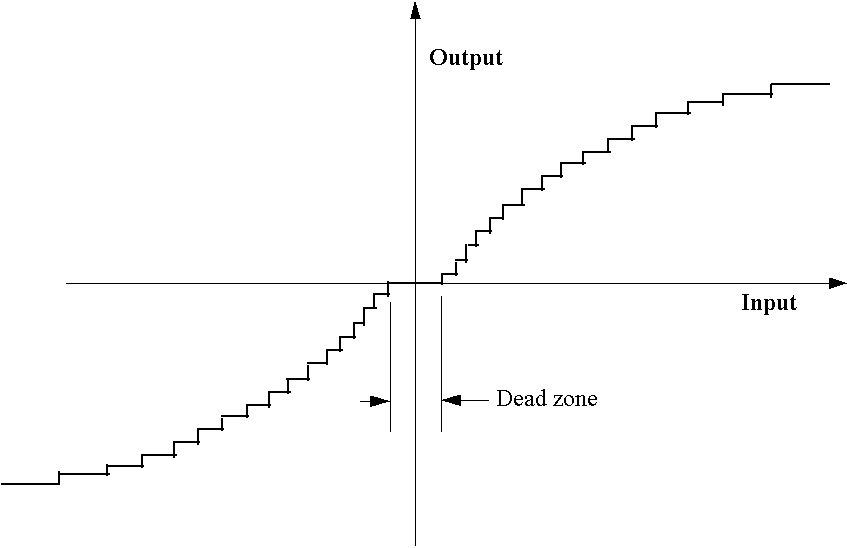
In addition to this frequency-dependent quantisation it is possible to further reduce the number of quantising steps needed to describe the range of DCT coefficient values by using a non-linear quantising law i.e. amplitude dependent. Referring to Fig. 5 it is seen that large value coefficients are more coarsely coded than small value ones. The quantiser output codeword length is thus reduced relative to the input. Also all values within the dead band are set to zero.
Figure 5
Non-linear quantiser characteristic

When coding complex pictures it may be necessary to change the quantisation matrix values for every DCT block and the MPEG standards allow for this. Obviously for the decoder to keep track of what the encoder is doing, any changes to the matrix must be transmitted to it.
In summary the quantising strategy implemented in a typical MPEG video encoder can be very complex, however it is one of the keys to obtaining good picture quality at modest bit rates. Different approaches to the quantising strategy by manufacturers could result in different levels of performance.
Return to DTTB Tutorial Table Of Contents