3.5.8 Run length coding
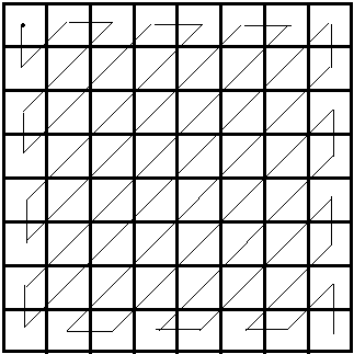
As already discussed the effect of the various coding techniques is to reduce most of the coded values that need to be transmitted to a value of zero or a near-zero value. In practice when the processed DCT coefficients are read out of their store in serial form the output bit stream can be expected to contain strings of "0"s. The likelihood of this occurring can be improved by reading out the store in "zig-zag" fashion as depicted in Fig. 6.
Figure 6
Scanning of 8 x 8 pixel block

This process groups the low- and mid-frequency coefficients (which are more likely to have zero values) together by reading out the store in terms of ascending frequency coefficients. In addition to this zig-zag scanning MPEG-2 allows for an alternative method.
Rather than transmitting the string of contiguous "0"s that typically results when the store is read out the run length coder sends a unique codeword in place of the string. As this codeword is shorter than the run of "0"s it represents the coding bit rate is reduced.
3.5.9 Variable length coding
Variable length coding (VLC) takes advantage of the fact that certain coded values are going to occur more often than others after the picture frame has been subject to prediction, transform and quantisation coding. In particular these processes will give rise to a predominance of near-zero DCT coefficients (after quantising). If frequently occurring values are assigned short length codewords and infrequently occurring ones transmitted using longer codewords an effective bit-rate reduction will be obtained.
As an analogy if English text was being transmitted, "a, e, i" would be sent with short length codes, whereas "z" would be sent using a long codeword. A good example of this is Morse code.
VLC is also referred to as Entropy coding. Note that in itself VLC is a lossless coding technique.
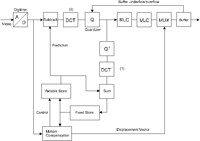
Figure 7
Basic MPEG video encoder
3.5.10 MPEG video encoder
Referring to Fig. 7, the feedback loop which simulates the decoder now includes the inverse quantiser and DCT processes. Following the RLC and VLC units the motion compensation vector information is multiplexed into the bit stream. As the codewords are of variable length a buffer has to be employed to allow the bit stream is transmitted at a uniform rate. To prevent the buffer overfilling or emptying a feedback loop provides an additional control input to the quantiser. If the buffer is nearing its capacity the quantiser is instructed to code the coefficient values more coarsely i.e. reduce the number of bits needed to describe the range of values. Conversely if the quantiser is near empty the quantiser can add dummy codewords.
3.5.11 I, B & P-frames
In MPEG parlance the intra-frame coded pictures (refer to § 3.2) when transmitted are referred to as I-frames and the inter-frame predicted pictures (§ 3.1) are referred to as P-frames. As already mentioned an I-frame is always initially sent to provide a reference for the decoder with P-frames subsequently sent. Additionally MPEG provides for "bidirectional predicted" frames to be sent, interspersed between the I- and P-frames. These are referred to as B-frames. This is depicted in
Fig. 8.
Figure 8
I, B & P-frames
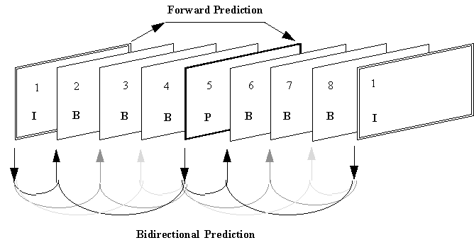
The predicted frame (5) is derived from the intra-frame (1) initially sent, i.e. frame (1) becomes the "previous frame" and frame (5) the "current frame" in the description contained in § 3.5.4.
In this example 3 B-frames are sent between the I- and P-frames. Frames (2), (3) and (4) are interpolated from both the past frame (1) and the future frame (5). (Looking into the "future" can be done by storing all the frames before processing.) Block matching (motion compensation) occurs using picture information from both frames (1) and (5). One of the advantages of bidirectional interpolation is that the future frame can provide information about a scene change that may not have been present in the past frame. Since B-frames can be derived in the decoder without the frame as such being sent by the encoder the information rate is reduced (higher compression). The disadvantage of using B-frames is the additional processing complexity and memory requirements necessary, particularly in the cost-sensitive decoder.
I, B & P-frames are also called I, B & P-pictures.
3.5.12 The MPEG-2 coding structure
MPEG-2 specifies three types of streams:
Packetised Elementary Stream
Program Stream
Transport Stream
3.5.13 Packetised elementary stream
Fig. 9 shows the structure of an elementary stream packet.
Figure 9
Packet structure
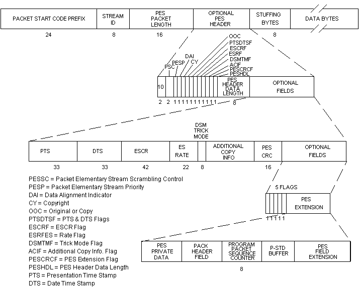
Start code prefix
This has a fixed value of $00 $00 $01 as described above.
Stream ID (identification)
Each type of stream has a particular value:
|
$BF |
Private 2 |
|
$C0 - $DF |
Audio Stream Number. |
|
$E0 - $EF |
Video Stream Number. |
|
$F0 - $FF |
Data Stream Number. |
Packet length
This gives the length of the packet - the maximum size can be 65 536 bits.
Buffer size
This field can contain the size of the buffer required in the decoder.
3.5.14 Actual Systems
The ATSC 6 MHz system limits the values for various MPEG-2 parameters. It supports 2 scanning formats. One has 720 active lines 1280 pels per active line, and 60 frames per second scanned progressively. The second uses interlace scanning with 1080 active lines with 1440 or 1920 pels per active line at 60 (59.94) fields per second. Both formats also support scanning at 24 (23.98), and 30 (29.97 ) frames per second. This system allows only the use of the Main Profile at the High Level. Other systems assume the use of the SNR Scalability Profile at the Main Level for Standard Definition Television, and the Main Profile at the High-1440 level.
3.5.15 Error Protection
For outer coding most systems considered for use in the DTTB environment use the Reed-Solomon method. The system for 6 MHz uses Reed-Solomon at (207,187). The other systems use Reed -Solomon at (204,188). Future applications may utilize other Reed-Solomon structures.
3.6 MPEG-2 video coding
3.6.1 Video bit stream
figure 10
Sequence header

|
SHC - Sequence_header_code (32 bits) |
|
|
HSV - Horizontal_size_value (12 bits) |
|
|
VSV - Vertical_size_value (12 bits) |
|
|
ARI - Aspect_ratio_information (4 bits) |
|
|
FRC - Frame_rate_code (4 bits) |
|
|
BRV - Bit_rate_value (18 bits) |
|
|
MB - Marker_bit (1 bit) |
|
|
VBS - Vbv_buffer_size (10 bits) |
IQM - Intra_quantizer_matrix (8*64) bits |
|
CPF - Constrained_parameter_flag (1 bit) |
LNIQM - Load_non_intra_quantizer_matrix(1 bit) |
|
LIQM - Load_intra_quantizer_matrix(1 bit) |
NIQM - Non_intra_quantizer_matrix (8*64) bits |
figure 11
Sequence extension

ESC - Extension_start_code (32 bits)
ESCI - Extension_start_code_identifier (4 bits)
PALI - Profile_and_level_indication (8 bits)
PS - Progressive_sequence (1 bit)
CF - Chroma_format (2 bits)
HSE - Horizontal_size_extension (2 bits)
VSE - Vertical_size_extension (2 bits)
BRE - Bit_rate_extension (12 bits)
MB - Marker_bit (1 bit)
VBSE - Vbv_buffer_size_extension (8 bits)
LD - Low_delay (1 bit)
FREN - Frame_rate_extension_n (2 bits)
FRED - Frame_rate_extension_d (5 bits)
Extension and user data
This description relates to the first "Extension & User Data" block encountered in the bit stream.
Extension data
Extension start code
Quant matrix extension
Picture display extension
Picture spatial scalable extension
Picture temporal scalable extension
Copyright extension
User data
figure 12
Sequence display extension

|
ESC - Extension_start_code (32 bits) |
|
|
ESCI - Extension_start_code_identifier (4 bits) |
|
|
VF - Video_format (3 bits) |
|
|
CD - Colour_description (1 bit) |
|
|
CP - Colour_primaries (8 bits) |
|
|
TC - Transfer_characteristics (8 bits) |
|
|
MC - Matrix_coefficents (8 bits) |
MB - Marker_bit (1 bit) |
|
DHS - Display_horizontal_size (14 bits) |
DVS - Display_vertical_size |
figure 13
Group of pictures header

GSC - Group_start_code (32 bits)
TV - Time_code (25 bits)
CG - Closed_gop (1 bit)
BL - Broken_link (1 bit)
figure 14
Picture header
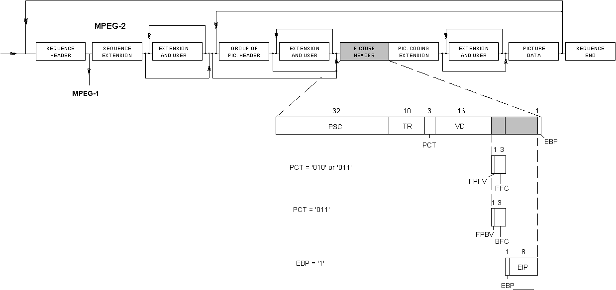
|
PSC - Picture_start_code (32 bits) |
|
|
TR - Temporal_reference (10 bits) |
|
|
PCT - Picture_coding_type (3 bits) |
|
|
VD - Vbv_delay (16 bits) |
|
|
FPFV - Full_pel_forward_vector (1 bit) |
|
|
FFC - Forward_f_code (3 bits) |
|
|
FPBV - Full_pel_backward_vector(1 bit) |
EPB - Extra_bit_picture (1 bit) |
|
BFC - Backward_f_code (3 bits) |
EIP - Extra_information_picture (8 bits) |
figure 15
Picture coding extension
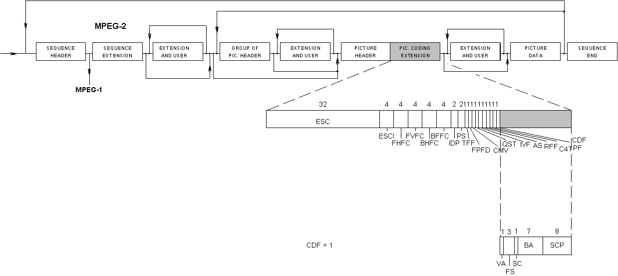
ESC - Extension_start_code
ESCI - Extension_start_code_identifier
FHFC - Forward_horizontal_f_code
FVFC - Forward_vertical_f_code
BHFC - Backward_horizontal_f_code
IDP - Intra_dc_precision
PS - Picture_structure
TFF - Top_field_first
FPFD - Frame_pred_frame_dct
CMV - Concealment_motion_vectors
QST - Q_scale_type
IVF - Intra_vic_format
AS - Alternate_scan1
RFF - Repeat_first_field
C4T - Chroma_420_type
PF - Progressive_frame
CDF - Composite_display_flag
VA - V_axis
FS - Field_sequence
SCBA - Sub_carrier_burst_amplitude
SCP - Sub_carrier_phase
figure 16
Sequence end

SEC - Sequence_end_code (32 bits)
References
Return to DTTB Tutorial Table Of Contents