4.5 The packetisation approach and functionality
4.5.1 Overview
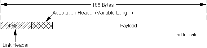
figure 35
Transport Packet
A DTTB communication system transport bit stream can consist of either fixed length packets or variable length packets. The packetisation approach described in this section is based on fixed length packets with a fixed and a variable component to the header field as illustrated in Fig. 35.
In this approach, based on MPEG-2 syntax, each packet consists of 188 bytes. The choice of this packet size is motivated by a few factors. The packets need to be large enough so that the overhead due to the transport headers does not become a significant portion of the total data carried. They should also not be so large that the probability of packet error becomes significant under standard operating conditions (due to inefficient error correction). It is also desirable to have packet lengths appropriate to the block sizes of typical, block oriented error correction approaches, so that packets may be synchronized to error correction blocks, and the physical layers of the system can aid the packet level synchronization process in the decoder. Another motive for the particular packet length selection is interoperability with the ATM format. The general philosophy of this approach is to transmit a single DTTB transport packet in four ATM cells.
The contents of each packet and the nature of the data it is carrying are identified by the packet headers. The packet header structure is layered and may be described as a combination of a fixed length link layer and a variable length adaptation layer. Each layer serves a different functionality similar to the link and transport layer functions in the OSI layers of a communications system. This link and adaptation level functionality is directly used for the terrestrial link on which the DTTB bit stream is transmitted. However, these headers could also be completely ignored in a different system (e.g. ATM), in which the DTTB bit stream is just the payload to be carried. In this environment, the DTTB bit stream headers would serve more as an identifier for the contents of a data stream rather than as a means for implementing a protocol layer in the overall transmission system.
The syntax elements of a possible system transport layer bit stream are defined for the purpose of exploring the requirements of such a system. It is understood that while most syntax elements are expected to trigger a response in the transport decoder, all syntax elements need to be recognized at some level of the receiver.
4.5.2 The "link" layer
figure 36
Link Header Format
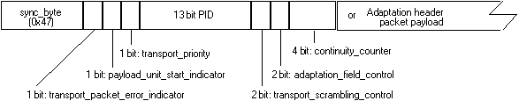
The link layer is implemented using a four byte header field. Fig. 36 shows a possible link layer header with functionality assigned to each bit. Table 6 provides a description of each function. The general functions may not all necessarily apply to a DTTB channel, but are useful for providing interoperability (transmitting the same bit stream over other links, including cable links, computer networks, satellite distribution systems, etc.).
Table 6
Link Header Format
|
field |
Function/Usage |
|
sync_byte (Value: 0x47) |
Packet synchronization |
|
transport_packet_error_indicator |
Indicates if packet is erroneous;
0®
no error |
|
payload_unit_start_indicator |
Indicates if a PES packet header of the start of a table containing program specific information (PSI) is present in the payload of the packet. The PES packet header always begins the payload of the packet. The starting byte of the PSI table in the packet is indicated using a pointer field.
0®
no PES header or start of PSI table present. |
|
transport_priority |
Priority indicator at input to transmission channels/networks which support prioritization.
0®
lower priority. transmission either by assignment to a carrier with higher power or to a packet with greater error protection, allows routing to path with appropriate priority.) |
|
PID |
Packet Identifier for multiplex/demultiplex. |
|
transport_scrambling_control |
Indicates the descrambling key to use for the packet.
00®
not scrambled. |
|
adaptation_field_control |
Indicates if an adaptation field follows.
00®
reserved. |
|
continuity_counter |
Increments by one for each packet within a given PID and transport priority. If two consecutive transport packets of the same PID have the same continuity_counter value and the adaptation_field_control equals 01 or 11, the two transport packets are considered duplicate.Used at the decoder to detect lost packets. Not incremented for packets with adaptation_field_control of 00 or 10. |
Packet synchronization is enabled by the sync_byte which is the first byte in a packet. The sync_byte has the same fixed, preassigned, value for all DTTB bit streams. In some implementations of decoders the packet synchronization function may be done at the physical layer of the communication link (which precedes the packet demultiplexing stage). In this case the sync-byte field may be used for verification of packet synchronization function. In other decoder implementations this byte may be used as the primary source of information for establishing packet synchronization.
An important element in the link header is a 13 bit field called the PID (Packet Identifier). This provides the mechanism for multiplexing and demultiplexing bit streams, by enabling identification of packets belonging to a particular elementary or control bit stream. Since the location of the PID field in the header is always fixed, extraction of the packets corresponding to a particular elementary bit stream is very simply achieved once packet synchronization is established by filtering packets based on PIDs. The fixed packet length makes for simple filter and demultiplexing implementations suitable for high speed transmission systems.
Error detection can be enabled at the packet layer in the decoder through the use of the continuity_counter field. At the transmitter end, the value in this field cycles from 0 through 15 for all packets with the same PID that carry a data payload (as will be seen later, the transport allows you to define packets that have no data payload). At the receiver end, under normal conditions, the reception of packets in a PID stream with a discontinuity in the continuity_counter value indicates that data has been lost in transmission. The transport processor at the decoder then signals the decoder for the particular elementary stream about the loss of data. The MPEG-2 specification does allow the continuity_counter to be discontinuous in order to accommodate local insertion of data packets and splicing. As a consequence, the continuity_counter can be discontinuous even in an error-free transmission.
Because certain information (such as headers, time stamps, and program maps) is very important to the smooth and continuous operation of a system, the transport system should provide a means of increasing the robustness of this information to channel errors by providing a mechanism for the encoder to duplicate packets. Those packets that contain important information would be duplicated at the encoder. At the decoder, the duplicate packets are used if the original packet was in error or are dropped. Semantics for identifying duplicate packets are described in the description of the continuity-counter.
The transport format allows for scrambling of data in the packets. Each elementary bit stream in the system can be scrambled independently. One approach to an universal standard would be to specify the descrambling approach to be used but not specify the descrambling key and how it is obtained at the decoder. The key must be delivered to the decoder within a time interval of its usefulness. A portion of the "private" data capacity within the DTTB data stream could be utilized to carry the required conditional access associated data. Two possible solutions would be 1) as a separate private stream with it's own PID, or 2) a private field within an adaptation header carried by the PID of the signal being scrambled. The security of the conditional access system can be ensured by encrypting the descrambling key when sending it to the receiver, and by updating the key frequently. There need not be any system imposed limit on the number of keys that can be used and the rate at which these may be changed. The only requirement that might be placed on a receiver to meet the standard is to have an interface from the decryption hardware (e.g., a Smart-card) to the decoder that meets the standardized interface specification.
Information in the link header of a transport packet can describe whether or not the payload in the packet is scrambled and if so, flags the key to be used for descrambling. The Header information in a packet is always transmitted in the clear, i.e., unscrambled. The amount of data to be scrambled in a packet can be made variable depending on the length of the adaptation header. It should noted that some padding of the adaptation field might be necessary for certain block mode algorithms.
Note that the general MPEG-2 transport definition provides the mechanism to scramble at two levels, within the PES packet structure and at the transport layer. Scrambling at the PES packet layer is primarily useful in the program stream where there is no protocol layer similar to the transport to enable this function.
Return to DTTB Tutorial Table Of Contents