4.5.3 The Adaptation layer
An MPEG-2 derived DTTB system adaptation header uses a variable length field. Its presence is flagged in the link level section of the header. The functionality of these headers is basically related to the decoding of the elementary bit stream that is extracted using the link level functions.
The presence of the adaptation header field is signalled in the adaptation_field_control of the link layer as described before. The adaptation header consists of information useful for higher level decoding functions and uses flags to indicate the presence of particular extensions to the field.
figure 37
Fixed-length Component of Adaptation Header

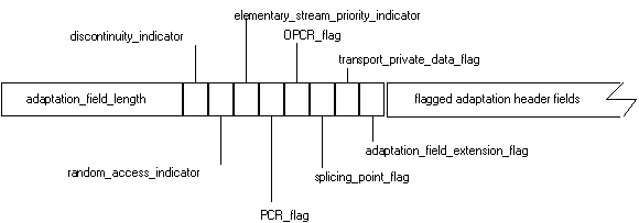
The header starts with a fixed length component that is present whenever the adaptation header is transmitted. The format is shown in Fig. 37.
The adaptation_field_length is a one byte field that specifies the number of bytes that follow it in the adaptation header. The adaptation header could include stuffing bytes after the last adaptation header component field. Stuffing bytes are not interpreted at the decoder. In this case, the adaptation_field_length also reflects the number of stuffing bytes. The value in the adaptation_field_length can also be used by the decoder to skip over the adaptation header, and to advance to the data payload when appropriate.
The presence of additional adaptation header fields is indicated by the state of the last five single bit flags shown in Fig. 37 where a value of 1 indicates that the indicated field is present. The first three (one-bit) flags do not produce extensions to the adaptation header and are described in Table 7.
Table 7
|
field |
Function/Usage |
|
discontinuity_indicator |
Indicates there is a discontinuity in the PCR values that will be received from this packets onwards. This occurs when bit streams are spliced. This flag should be used at the receiver to change the phase of the local clock. |
|
random_access_indicator |
Indicates that the packet contains data that can serve as a random access point into the bit stream. One example is to correspond to the start of sequence header information in the video bit stream. |
|
elementary_stream_priority_indicator |
Logical indication of priority if the data being transmitted in the packet. |
The other components of the adaptation header appear based on the state of the flags.
Synchronization of the decoding and presentation process for the applications running at a receiver is a particularly important aspect of real time digital data delivery systems. Since received data is expected to be processed at a particular rate (to match the rate at which it is generated and transmitted), loss of synchronization leads to either buffer overflow or under flow at the decoder, and as a consequence, loss of presentation/display synchronization. The problems in dealing with this issue for a digital compressed bit stream are different from those for analogue conventional television. In analogue conventional television, information is transmitted for the pictures in a synchronous manner, so that one can derive a clock directly from the picture synchronization information. In a digital compressed system the amount of data generated for each picture is variable (based on the picture coding approach and complexity), and timing cannot be derived directly from the start of picture data. Indeed, there is really no natural concept of synchronization pulses (that one is familiar with in analogue conventional television) in a digital bit stream.
The solution to this issue is to transmit timing information in the adaptation headers of selected packets, to serve as a reference for timing comparison at the decoder. This is done by transmitting a sample of a 27 MHz clock in the program_clock_reference (PCR) field, which indicates the expected time at the completion of the reading of the field from the bit stream at the transport decoder. The phase of the local clock running at the decoder is compared to the PCR value in the bit stream at the instant at which it is obtained, to determine whether the decoding process is synchronized. In general, the PCR from the bit stream does not directly change the phase of the local clock but only serves as an input to adjust the clock rate. Exceptions might be during channel change and insertion of local programming. Note that the audio and video sample clocks in the decoder system are locked to the system clock derived from the PCR values. This allows simplification of the receiver implementation in terms of the number of local oscillators required to drive the complete decoding process, and has other advantages such as rapid synchronization acquisition.
figure 38
PCR and OPCR Header Format

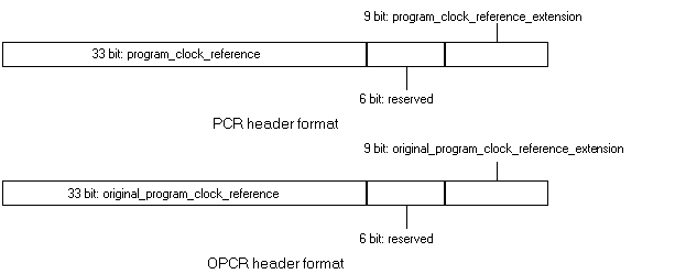
The PCR and OPCR fields are described in Fig. 38 and Table 8.
Table 8
|
field |
Function/Usage |
|
PCR |
Indicates intended time of arrival of last byte of the program_clock_reference_extension at the target decoder. Used for synchronization of the system decoding process. This field can be modified during the transmission process (e.g. the PCR will be transmitted at least once every 100 milliseconds.). |
|
OPCR |
Indicates intended time of arrival of last byte of the original_program_clock_reference_extension at the target decoder for a single program. This field is not modified during the transmission process. (May be used for recording and playback of single programs.) |
The total PCR value is based on the state of a 27 MHz clock. The 9 bit extension field cycles from 0 to 299 at 27 MHz at which point the value in the 33 bit field is incremented by one. This results in the 33 bit field being compatible with the 33 bit field used for the 90 kHz clock in MPEG-1. The cycle time of the PCR is approximately 26 hours.
Figure 39
transport_private_data and adaptation_field-extension Header Format

The transport_private_data and adaptation_field_extension fields are described in Fig. 39 and Table 9.
Table 9
|
field |
Function/Usage |
|
transport_private_data |
For private data. |
|
adaptation_header_extensions |
For future extensions of the adaptation header. |
The splice_countdown field is useful for downstream (local) program insertion. The splice_countdown field, described in Table 10 is a one byte field that is present if the splicing_point_flag is set.
Table 10
|
field |
Function/Usage |
|
splice_countdown |
Indicates the number of packets in the bit stream with the same PID as current packet until a splicing point packet. The splicing point packet is defined as the packet containing a point in the elementary bit stream from which point onwards data can be removed and replaced by another bit stream. Transmitted as a 2's compliment value. (Use for supporting of insertion of local programming and packets.) |
Return to DTTB Tutorial Table Of Contents